Electromagnetic analysis is no longer reserved for R&D teams with their own simulation department. In many companies it has become a routine part of design work – especially where the result depends on losses, heating, forces, inductance, impedance or high-frequency behaviour. Whenever a design needs to be verified before a prototype is built, a good simulation tool saves both time and budget.
This is exactly where the EMWORKS platform comes in. What makes it interesting is that it doesn't cover just one narrow discipline, but several types of electromagnetic problems within a single product family. In practice, one team can work on a solenoid, another on an antenna and a third on an electric motor design – all while using a similar approach to modelling and evaluating results.
For engineering and R&D companies, one more thing matters: electromagnetic simulation is not an isolated island. It needs to connect to the CAD model, materials, thermal loads, motion and sometimes the mechanical response as well. This interconnection is one of the main reasons why EMWORKS is being talked about more and more.
What EMWORKS brings to the CAD workflow and to everyday simulation
EMAG is electromagnetic simulation software designed for several categories of problems, from low and medium frequencies through to high-frequency applications and electric machine design. According to the available product information, it covers everything from DC and low-frequency phenomena up to high frequencies in bands of around 300 GHz and above, depending on the module and type of analysis.
From a practical point of view, it is valuable that the software is built around the design environment. Users don't have to jump between a separate CAD world and a separate simulation world every time the geometry changes slightly. With some editions and modules, you work directly in an environment linked to CAD, which shortens iterations and simplifies model management. For 2D electromagnetic problems, there is also a solution embedded in SOLIDWORKS, while other parts of the portfolio are commonly paired with Autodesk Inventor.
That is good news above all for teams that want to make simulation part of the everyday design process rather than a final check at the end. An overview of the modules is available on the 4CAD solution page, and the wider context of CAD workflows and related tools can also be followed on Techcad.cz.
Overview of the EMAG, RF & Microwave and Motors modules
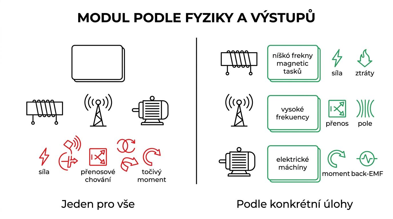
The basic orientation is simple: one platform, three different areas of use. What decides is the frequency range, the physical nature of the problem and the outputs you expect.
| Module | Type of problem | Typical applications | Common outputs |
|---|---|---|---|
| EMAG | low and medium frequencies | solenoids, transformers, busbars, fuses, actuators | magnetic flux density, forces, inductance, losses, heating |
| RF & Microwave | high frequencies | antennas, filters, connectors, RF and microwave components, high-speed interconnects | S-parameters, fields, resonances, impedance, matching |
| Motors | electric machines | BLDC, PMSM and other types of motors and generators | torque, back-EMF, losses, inductance, flux density |
This split is also practical when making decisions within a team. There is no need to look for a universal solver for absolutely everything. It is much better to choose the module that matches the specific problem and delivers the right outputs without unnecessary compromises.
The EMAG module for low and medium frequencies in engineering practice
EMAG targets problems involving electromagnetic fields at low and medium frequencies. That covers a wide range of devices, from classic solenoids and relays to transformers, fuses, busbars and all kinds of industrial actuators. It is an area where electrical design often meets the mechanical function of a product.
The big advantage of this kind of simulation is that the engineer doesn't just get a nice colourful field plot. They get data to base decisions on. What force will the actuator produce? Where will the highest losses occur? Is a critical spot overheating? What happens if the core material changes or the air gap is adjusted? In real-world development, these questions are often worth more than the calculation itself.
EMAG also frequently deals with motion coupling for devices with moving parts. This is essential for motors, actuators and systems where the position of a component significantly changes the magnetic circuit. Add thermal and structural coupling, and you can also track the knock-on effects – mechanical stress, deformation or heat dissipation.
Typical applications include:
- solenoids
- busbars
- transformers
- fuses
- relays and actuators
In exactly these applications, the benefit of simulation can be measured very quickly: fewer physical prototypes, fewer blind modifications and better insight into what is really happening inside the device.
The RF & Microwave module for antennas, microwave components and high frequencies
Once a design moves into the high-frequency domain, the rules of the game change. It is no longer enough to look at current distribution or magnetic force. What matters now are reflections, coupling, resonances, radiation and transmission parameters. This is where RF & Microwave comes in – a full-wave 3D solution for high-frequency electronic structures.
The module is suited to antennas, RF and microwave components, filters, connectors, transitions, mm-wave components and high-speed interconnects. Instead of a simple yes-or-no answer, it gives a detailed view of how the structure behaves across the operating band. The design engineer or RF specialist can evaluate S-parameters, matching, the field around the component and the sensitivity of the design to changes in geometry.
Antennas and connectors illustrate this well. Even a small change in shape, dielectric or dimensions can significantly shift the behaviour of the whole system. Simulation therefore doesn't only help with final verification – it is highly valuable in the early stages, when the right topology is still being worked out.
Another practical point is that high-frequency analysis doesn't have to stop at the electromagnetic result. Selected solutions also offer electro-thermal coupling or auxiliary tools for designing transmission lines. This makes sense especially where high frequencies, dense component layouts and thermal stability requirements come together.
In short, RF & Microwave isn't just about antenna simulation. It is a tool for designing the functional high-frequency behaviour of the entire structure.
The Motors module for designing electric motors and electrical machines
Electric motor design is a discipline in its own right. Calculating the field in a single cross-section is not enough. You need to track torque, losses, back electromotive force, inductance, air-gap behaviour and performance over time. This is precisely the kind of work the Motors module is designed for.
Its strength lies in combining analytical methods with the finite element method, depending on what suits a given design stage best. In practice, this is extremely useful. Early in development, the team needs to compare variants quickly. Later comes more detailed validation, finer tuning of the geometry and checking of operating conditions. A single type of solver is often not enough for all of that.
Users also appreciate the design wizard, known as MotorWizard, which helps calculate the parameters that matter for machine design. These include the torque curve, air-gap flux density, back-EMF and phase inductance. These are not academic values but the data used to decide on geometry, winding, materials and operating strategy.
When choosing a module for electrical machines, it is worth considering several points:
- Machine type: whether it is a BLDC, PMSM, generator, actuator or special rotating device
- Required outputs: torque, losses, efficiency, back-EMF, inductance, thermal response
- Development stage: quick comparison of variants, detailed FEA validation or a combination of both
- Link to mechanics: rotor, air gap, motion, vibration and the connection to real-world loads
When a motor is developed without this layer of analysis, it often just means building prototype after prototype. With a properly set-up simulation workflow, some of these iterations can be moved into the virtual space, leaving physical tests for the verification that really matters.
Multiphysics coupling: heat, motion and mechanical response
In electromagnetic analysis, it is a big mistake to stop at the field alone. A real product does not behave in isolation. Losses turn into heat, heat changes material properties, motion changes the magnetic circuit and mechanical loads can affect reliability and service life.
That is why it is valuable that, in practice, EMWORKS is also associated with multiphysics coupling. For low-frequency problems, this can mean a link to thermal losses, kinematics or deformation. For high-frequency applications, an electro-thermal check makes sense. And for motors, it is natural to look at the electromagnetic design together with mechanics and cooling.
When a team builds a sensible workflow, it often proceeds as follows:
- pick a critical problem with a measurable benefit
- prepare clean geometry and correct material models
- compare the simulation with a reference measurement or a known state
- create a repeatable template for future projects
This way, simulation doesn't become a one-off experiment but a stable part of development.
How to choose the right EMWORKS module for your project
The best choice doesn't start with a module name, but with the question of what exactly you need to calculate. If you are dealing with magnetic forces, inductance, losses and device behaviour at low to medium frequencies, EMAG is the logical choice. If you are interested in antennas, radiation, transmission characteristics and S-parameters, RF & Microwave is the right fit. If an electrical machine is at the heart of the design, Motors makes the most sense.
It is also worth thinking about how the results will be used further down the line. Sometimes a one-off validation is enough. Other times the goal is regular parametric work with variants. And sometimes the simulation step becomes a fixed stage before every design release. This is where it becomes clear whether the software fits well into the everyday CAD workflow and whether it can offer fast iteration without needlessly complicated preparation.
For a pilot deployment, it is ideal to choose one representative project – for example a busbar under load, an RF connector or a small motor for which measurements already exist. This type of problem is the best way to verify accuracy, speed of work and how well the team handles the interpretation of results.
A more detailed overview of the product line can be found on 4-cad.cz, and technical materials on the high-frequency and 2D solutions are also available on the official EMWorks website. If your company already works with Autodesk Inventor or SOLIDWORKS and electromagnetic analysis is to become part of everyday development, this is exactly the type of tool worth testing on a real model, not just on a sample demonstration.